Configure IS-IS Flexible Algorithms
Traditional routing protocols like IS-IS and OSPF make forwarding decisions based on a single metric, typically configured or derived from interface bandwidth. While this approach works well for many networks, it doesn’t account for the diverse requirements of applications that need low-latency paths, require high bandwidth without latency considerations, or have specific compliance or security constraints.
IS-IS Flexible Algorithm (Flex-Algo) addresses this limitation. It allows multiple routing topologies to coexist in the same network, each optimized for different metrics or constraints. Instead of running separate routing protocol instances, Flex-Algo enables a single IS-IS deployment to compute multiple shortest-path trees using different optimization criteria.
Tip
ISIS is not the only IGP to support flexible algorithms. OSPF does support them as well. Flexible algorithms were initially introduced in RFC 9350: IGP Flexible Algorithm
In this exercise, you’ll use the IS-IS Flexible Algorithm to implement delay-based routing. You’ll configure routers to compute paths based on link delay instead of the default IGP metric, enabling latency-sensitive traffic to follow optimal low-delay paths while regular traffic continues to use bandwidth-optimized routes.
Expert
This is an expert-level challenge lab. We’ll give you guidelines, but you’re mostly on your own.
Device Requirements
Use any device supported by the netlab IS-IS and Segment Routing configuration modules for the routers in your lab. The device should support IS-IS flexible algorithms and delay metric.
Starting the Lab
You can start the lab on your own lab infrastructure or in GitHub Codespaces (more details):
- Change directory to
advanced/12-delay - Execute netlab up.
- Log into lab routers with netlab connect and verify their configuration.
Tip
Use Arista EOS containers with GitHub Codespaces. You won’t be able to load the kernel drivers needed by FRRouting or VyOS containers, and SR Linux containers need a license to run MPLS.
Existing Routing Protocol Configuration
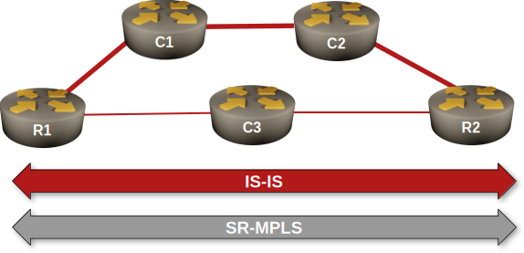
- When starting the lab, netlab configures IPv4 addresses (details), IS-IS, and SR-MPLS on the lab routers.
- All routers are IS-IS level-2 routers in area 49.0001 (details)
- The R1-C1, C1-C2, and C2-R2 are high-bandwidth links with IS-IS metric 5 (details).
- The R1-C3 and C3-R2 are low-bandwidth, low-latency links with IS-IS metric 10 (details).
The Problem
After the IS-IS adjacencies are established, router R1 will reach R2 over the path with the lowest cost (the high-bandwidth path R1-C1-C2-R2):
Traceroute to R2 starting on R1, Arista cEOS
r1#traceroute ip r2

traceroute to r2 (10.0.0.2), 30 hops max, 60 byte packets

1. c1 (10.1.0.1)0.043 ms0.009 ms0.008 ms
2. c2 (10.1.0.6)1.011 ms1.020 ms1.150 ms
3. r2 (10.0.0.2)1.537 ms1.832 ms2.119 ms
We want to enable a second path in our network. The path should enable R1 to reach R2 over the low-latency path (R1-C3-R2). You will use a flexible-algorithm-based solution to create that path.
Configuration Hints
Configure a delay metric-based flexible algorithm in your network:
- At least one router must define the flexible algorithms1; the algorithm definition is propagated to all other routers via IS-IS TLVs/OSPF LSAs. Configure your algorithm on R1.
- Algorithm IDs 0 to 127 are reserved. Define algorithm 128, with a priority of 1002 and the label of LOW_LATENCY.
Tip
On Arista EOS, you’ll find the flex-algo section in the router traffic-engineering configuration block.
- The router that defines the algorithm should advertise it into the IGP. We are using a pure level-2 IS-IS network; advertise your algorithm only into the level-2 backbone.
Tip
On Arista EOS, you’ll have to configure that in the segment-routing mpls part of the router isis configuration.
- Even if only one router defines the algorithm, all other routers that want to participate in that algorithm must declare it. We defined the algorithm on R1, so we have to declare it on R2 and C2.
- All other routers that want to participate in the constrained graph represented by this flex-algo must announce their intent.
Tip
On Arista EOS, you use the same command you used to advertise the algorithm into the IGP, but without the advertised option.
Finally:
- Assign a delay based metric on all interfaces in the path R1-C3-R2. Use a value of 500 microseconds.
Tip
Use the traffic-engineering interface configuration command on Arista EOS
- For verification purposes, assign a second node Segment ID (SID) specifically referencing algorithm 128 on R2’s loopback. Use a unique label; the SID labels advertised in SR-MPLS TLVs are global and must be recognized by every node in the network.
Validation
You can use a Flex-Algo-Aware MPLS traceroute to check the path from R1 to R2 using the LOW_LATENCY algorithm. If your configuration is correct, R1 must reach R2 through C3.
Flex-Algo-Aware MPLS traceroute from R1 to R2.
r1#traceroute mpls segment-routing ip 10.0.0.2/32 algorithm LOW_LATENCY
! Warning: NTP synchronization is required for 1-Way time measurement accuracy.
LSP traceroute IS-IS segment-routing to 10.0.0.2/32 , algorithm LOW_LATENCY
  via 10.1.0.13, label stack: [901000]
  1  10.1.0.13         MTU 1500  RTT:0.853ms   1-Way:0.563ms     success: label switched
     downstream information (DSMAP) 1:
        interface address: 10.1.0.18
        IP address: 10.1.0.18
        label stack: [implicit-null]
  2  10.1.0.18         RTT:1.333ms   1-Way:0.838ms     success: egress ok
However, the scenic journey is usually more fun: let’s explore IS-IS data structures and gradually discover how they’re used to create the label-switched path from R1 to R2 via C3.
As soon as you configure an advertised Flex-Algo on R1, you can check its presence in the sub-TLVs of R1’s LSP. Notice that R1 advertises that it uses two algorithms: zero (the IGP default) and 128 (the LOW_LATENCY algorithm).
Contents of R1.00-00 LSP on PE1 running Arista EOS
r1#show isis database r1.00-00 detail
Legend:
H - hostname conflict
U - node unreachable

IS-IS Instance: Gandalf VRF: default
  IS-IS Level 2 Link State Database
    LSPID                   Seq Num  Cksum  Life Length IS  Received LSPID        Flags
    r1.00-00                      5  52940   978    216 L2  0000.0000.0001.00-00  <>
      LSP generation remaining wait time: 0 ms
      Time remaining until refresh: 678 s
      NLPID: 0xCC(IPv4)
      Hostname: r1
      Area addresses: 49.0001
      Interface address: 10.1.0.2
      Interface address: 10.1.0.14
      Interface address: 10.0.0.1
      IS Neighbor          : c3.00               Metric: 10
        IPv4 Neighbor Address: 10.1.0.13
        IPv4 Interface Address: 10.1.0.14
        Adj-sid: 100000 flags: [L V] weight: 0x0
      IS Neighbor          : c1.00               Metric: 5
        IPv4 Neighbor Address: 10.1.0.1
        IPv4 Interface Address: 10.1.0.2
        Adj-sid: 100001 flags: [L V] weight: 0x0
      Reachability         : 10.1.0.0/30 Metric: 5 Type: 1 Up
      Reachability         : 10.1.0.12/30 Metric: 10 Type: 1 Up
      Reachability         : 10.0.0.1/32 Metric: 10 Type: 1 Up
        SR Prefix-SID: 1 Flags: [N] Algorithm: 0
      Router Capabilities: Router Id: 10.0.0.1 Flags: []
        SR Local Block:
          SRLB Base: 965536 Range: 65536
        Area leader priority: 250 algorithm: 0
        Maximum SID depth:
          Base MPLS imposition (MSD type 1):  6
        SR Capability: Flags: [I]
          SRGB Base: 900000 Range: 65536
        Algorithms:  0, 128
        Flex Algo: Algorithm: 128 Metric: Min Unidirectional Delay Metric (1) Calc: SPF (0) Prio: 100
What about R2 and C3? They advertise they’re using algorithms zero and 128, but not the definition of algorithm 128:
Contents of R2.00-00 LSP on PE1 running Arista EOS
r1#show isis database r2.00-00 detail
Legend:
H - hostname conflict
U - node unreachable

IS-IS Instance: Gandalf VRF: default
  IS-IS Level 2 Link State Database
    LSPID                   Seq Num  Cksum  Life Length IS  Received LSPID        Flags
    r2.00-00                      5  61368   880    218 L2  0000.0000.0002.00-00  <>
      LSP received time: 2026-02-23 17:54:31
      Remaining lifetime received: 1199 s Modified to: 1200 s
      NLPID: 0xCC(IPv4)
      Hostname: r2
      Area addresses: 49.0001
      Interface address: 10.1.0.10
      Interface address: 10.1.0.18
      Interface address: 10.0.0.2
      IS Neighbor          : c3.00               Metric: 10
        IPv4 Neighbor Address: 10.1.0.17
        IPv4 Interface Address: 10.1.0.18
        Adj-sid: 100000 flags: [L V] weight: 0x0
      IS Neighbor          : c2.00               Metric: 5
        IPv4 Neighbor Address: 10.1.0.9
        IPv4 Interface Address: 10.1.0.10
        Adj-sid: 100001 flags: [L V] weight: 0x0
      Reachability         : 10.0.0.2/32 Metric: 10 Type: 1 Up
        SR Prefix-SID: 2 Flags: [N] Algorithm: 0
        SR Prefix-SID: 1000 Flags: [N] Algorithm: 128
      Reachability         : 10.1.0.8/30 Metric: 5 Type: 1 Up
      Reachability         : 10.1.0.16/30 Metric: 10 Type: 1 Up
      Router Capabilities: Router Id: 10.0.0.2 Flags: []
        SR Local Block:
          SRLB Base: 965536 Range: 65536
        Area leader priority: 250 algorithm: 0
        Maximum SID depth:
          Base MPLS imposition (MSD type 1):  6
        SR Capability: Flags: [I]
          SRGB Base: 900000 Range: 65536
        Algorithms:  0, 128
You can also use the show isis flex-algo command instead of digging through the arcane sub-TLVs in IS-IS LSPs:
IS-IS flex algorithms known to R1 running Arista cEOS
r1#show isis flex-algo

IS-IS Instance: Gandalf VRF: default

Algorithm   Advertised Level Metric    Selected
----------- ---------- ----- --------- --------
LOW_LATENCY yes        L2    min-delay r1
How about checking which routers participate in an algorithm? Arista cEOS has a command for that:
Routers participating in IS-IS flex algorithms, as displayed by R1 running Arista cEOS
r1#show isis flex-algo routers

IS-IS Instance: Gandalf VRF: default

Algorithm: LOW_LATENCY

Router Level Advertising Priority
------ ----- ----------- --------
c3     L2    no
r1     L2    yes              100
r2     L2    no
Finally, let’s see how the routers use SR-MPLS segment identifiers to build MPLS paths, starting with the prefix segments advertised by IS-IS:
IS-IS advertised SR-MPLS prefix segments as displayed on R1 running Arista cEOS
r1#show isis segment-routing prefix-segments

System ID: r1                   Instance: 'Gandalf'
SR supported Data-plane: MPLS                   SR Router ID: 10.0.0.1

Node: 6      Proxy-Node: 0      Prefix: 0       Total Segments: 6

Flag Descriptions: R: Re-advertised, N: Node Segment, P: no-PHP
                   E: Explicit-NULL, V: Value, L: Local, A: Proxy-Node attached
Segment status codes: * - Self originated Prefix, L1 - level 1, L2 - level 2, ! - SR-unreachable,
                      # - Some IS-IS next-hops are SR-unreachable
   Prefix                      SID   Label Type       Flags                        System ID       Level Protection  Algorithm
   ------------------------- ----- ------- ---------- ---------------------------- --------------- ----- ----------- -------------
*  10.0.0.1/32                   1  900001 Node       R:0 N:1 P:0 E:0 V:0 L:0      r1              L2    unprotected SPF
   10.0.0.2/32                   2  900002 Node       R:0 N:1 P:0 E:0 V:0 L:0      r2              L2    unprotected SPF
   10.0.0.2/32                1000  901000 Node       R:0 N:1 P:0 E:0 V:0 L:0      r2              L2    unprotected LOW_LATENCY
   10.0.0.3/32                   3  900003 Node       R:0 N:1 P:0 E:0 V:0 L:0      c1              L2    unprotected SPF
   10.0.0.4/32                   4  900004 Node       R:0 N:1 P:0 E:0 V:0 L:0      c2              L2    unprotected SPF
   10.0.0.5/32                   5  900005 Node       R:0 N:1 P:0 E:0 V:0 L:0      c3              L2    unprotected SPF
Did you notice R2 advertises two SIDs for the 10.0.0.2/32 prefix, one per algorithm? Want to see how those labels get installed into the MPLS forwarding table (LFIB)? Let’s do it:
Examine the MPLS LFIB on R1 running Arista cEOS
r1#show mpls lfib route 10.0.0.2/32 | begin 900
 IP    900002   [1], 10.0.0.2/32
                via M, 10.1.0.1, swap 900002
                 payload autoDecide, ttlMode uniform, apply egress-acl
                 interface Ethernet1
 IP    901000   [1], 10.0.0.2/32, algorithm LOW_LATENCY
                via M, 10.1.0.13, swap 901000
                 payload autoDecide, ttlMode uniform, apply egress-acl
                 interface Ethernet2
SR-MPLS usually uses the same label across the entire LSP (there’s no swapping of label values like in traditional LDP- or MPLS-TE-based networks). The label 900002 (mapped to SPF path toward 10.0.0.2/32) has C1 (10.1.0.1) as the next hop, while the label 901000 (mapped to LOW_LATENCY path toward 10.0.0.2/32) has C3 (10.1.0.13) as the next hop.
Finally, let’s see what the routing table entry for 10.0.0.2/32 looks like:
IP routing table entry for R2’s loopback on R1 running Arista cEOS
r1#show ip route 10.0.0.2/32 detail | begin 10.0.0.2
 I L2     10.0.0.2/32 [115/25] PM
           via 10.1.0.1, Ethernet1 r1 -> c1
The routing table entry still points to the SPF path (over C1 and C2); that’s why we had to use the MLPS traceroute to check the low-delay path.
Is there a way to make the router use the flex-algo paths for regular traffic? That’s the topic for the next flex-algo lab exercise.
Cheating
If you’re using Arista EOS, execute the netlab config -l r1,r2,c3 flex-algo.
Note: The exercise includes the supplementary configuration files for Arista EOS. These configuration snippets will not work with any other device.
Reference Information
Lab Wiring
| Origin Device | Origin Port | Destination Device | Destination Port |
|---|---|---|---|
| r1 | Ethernet1 | c1 | Ethernet1 |
| c1 | Ethernet2 | c2 | Ethernet1 |
| c2 | Ethernet2 | r2 | Ethernet1 |
| r1 | Ethernet2 | c3 | Ethernet1 |
| c3 | Ethernet2 | r2 | Ethernet2 |
Note: The interface names depend on the devices you use in the lab. The printout was generated with lab devices running Arista EOS.
Lab Addressing
| Node/Interface | IPv4 Address | IPv6 Address | Description |
|---|---|---|---|
| r1 | 10.0.0.1/32 | Loopback | |
| Ethernet1 | 10.1.0.2/30 | r1 -> c1 | |
| Ethernet2 | 10.1.0.14/30 | r1 -> c3 | |
| r2 | 10.0.0.2/32 | Loopback | |
| Ethernet1 | 10.1.0.10/30 | r2 -> c2 | |
| Ethernet2 | 10.1.0.18/30 | r2 -> c3 | |
| c1 | 10.0.0.3/32 | Loopback | |
| Ethernet1 | 10.1.0.1/30 | c1 -> r1 | |
| Ethernet2 | 10.1.0.5/30 | c1 -> c2 | |
| c2 | 10.0.0.4/32 | Loopback | |
| Ethernet1 | 10.1.0.6/30 | c2 -> c1 | |
| Ethernet2 | 10.1.0.9/30 | c2 -> r2 | |
| c3 | 10.0.0.5/32 | Loopback | |
| Ethernet1 | 10.1.0.13/30 | c3 -> r1 | |
| Ethernet2 | 10.1.0.17/30 | c3 -> r2 |
IS-IS Routing
IS-IS routers and areas:
| Node | Router ID | IS-IS Area | System ID | IS type |
|---|---|---|---|---|
| r1 | 10.0.0.1 | 49.0001 | 0000.0000.0001 | level-2 |
| r2 | 10.0.0.2 | 49.0001 | 0000.0000.0002 | level-2 |
| c1 | 10.0.0.3 | 49.0001 | 0000.0000.0003 | level-2 |
| c2 | 10.0.0.4 | 49.0001 | 0000.0000.0004 | level-2 |
| c3 | 10.0.0.5 | 49.0001 | 0000.0000.0005 | level-2 |
IS-IS links and metrics:
| Node | Interface | Circuit Type |
Metric | Network type |
Description |
|---|---|---|---|---|---|
| c1 | eth1 | 5 | point-to-point | c1 -> r1 | |
| eth2 | 5 | point-to-point | c1 -> c2 | ||
| c2 | eth1 | 5 | point-to-point | c2 -> c1 | |
| eth2 | 5 | point-to-point | c2 -> r2 | ||
| c3 | eth1 | 10 | point-to-point | c3 -> r1 | |
| eth2 | 10 | point-to-point | c3 -> r2 | ||
| r1 | eth1 | 5 | point-to-point | r1 -> c1 | |
| eth2 | 10 | point-to-point | r1 -> c3 | ||
| r2 | eth1 | 5 | point-to-point | r2 -> c2 | |
| eth2 | 10 | point-to-point | r2 -> c3 |